
Sensor Header Lead Plating Fixtures: Contact and Surface Treatment
Sensor-header plating fixtures protect leads and end faces for subsequent assembly
Bent sensor-header leads or damaged end faces during plating can affect subsequent connection and assembly. Winding and straightening also add lead handling. Rodee’s dedicated fixture uses locating grooves and metal balls for guidance, positioning and electrical contact, together with solution passages and local insulation to control the plated area.
Reduce winding and straightening around the connection area
Header leads need suitable positioning and end-face condition for subsequent soldering or bonding. Winding and straightening add handling, while collisions during barrel plating can deform the leads or damage their ends.
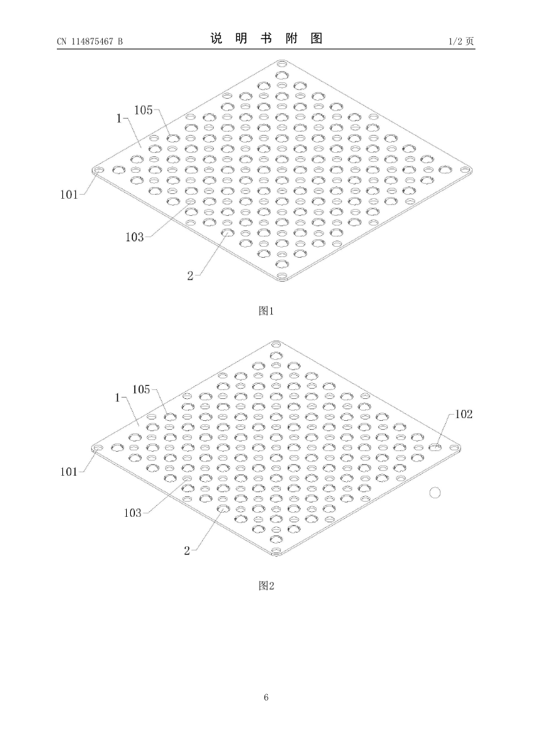
Locating grooves guide the leads, and metal balls position them and provide conductive contact, avoiding reliance on winding and post-plating straightening. Multiple clamping positions can be arranged on the fixture plate to constrain parts during batch treatment and reduce unnecessary lead handling.
Leave paths for solution flow and limit unwanted plating
Holding the parts is only one task: plating solution must also reach the treatment surfaces. Flow holes between locating grooves and open through-hole structures provide passages and reduce blind pockets where solution can collect.
Acid- and alkali-resistant insulating adhesive covers non-contact areas to limit deposition and material use on surfaces that do not require plating. Lead positioning, electrical contact, solution flow and local insulation work together during header-lead surface treatment.
Specify surface treatment around the subsequent assembly process
When purchasing pressure cores or related parts, consider lead position, length, end-face condition and treatment areas alongside range, medium, packaging and compensation. Identify the soldering or bonding areas on the assembly drawing where applicable.
For special lead or coating requirements, provide dimensions, the connection method and acceptance requirements to assess suitable parts and processing. Samples can be checked for lead dimensions, appearance and connection areas; volume supply can follow agreed coating, appearance and batch-documentation requirements for the subsequent process.
Patent documents
Read the patent description and claims · View the published PDF · Download PDF
Patent record and certificate
| Title on the certificate | 一种传感器管座引线电镀工装设备 |
|---|---|
| Patent type | Invention patent |
| Patent number | ZL 2021 1 0521672.7 |
| Filing date | 2021-05-13 |
| Grant publication date | 2023-10-20 |
| Grant publication number | CN 114875467 B |
| Certificate number | 6409199 |
| Inventor named on the certificate | 唐中山 (Tang Zhongshan) |
| Patentee named on the certificate | 唐中山 (Tang Zhongshan) |
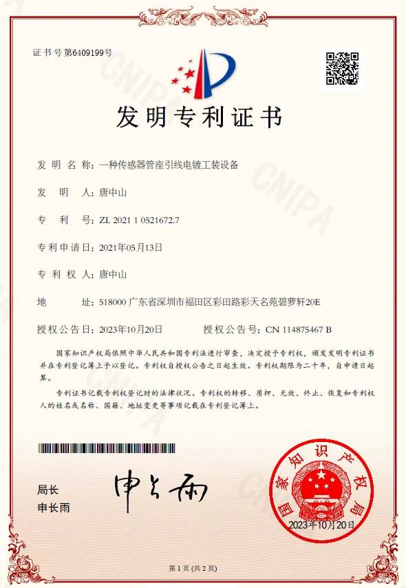
View the original certificate image
Integration questions
What information is needed for custom leads?
Provide lead position and dimension drawings, the subsequent soldering or bonding method, and requirements for end-face appearance, treatment areas and coating. Include the mating assembly drawing where available to identify connection areas and processing requirements.
Related products and technical support
Review pressure-core documents and confirm lead dimensions, surface treatment and assembly requirements for the intended connection process.
Contact Rodee Sensors for selection and technical documents · Back to the patent portfolio